
During the extended COVID quarantine this year, we took the opportunity to do a number of upgrades to Airship. We discussed a lot of them in this article, but we have gotten enough questions on the power system in particular that it merits its own discussion. This article will be closed-captioned for nerds, with a few extra-detail sections for those who want to dive into the kilowatts, amps, and volts.
Airship had a perfectly fine power system before. The house batteries were 12V AGM (absorbed glass mat – one of the more robust flavors of sealed lead-acid battery), with 660Ah (7.9kWh) capacity. To charge those batteries and to produce AC power from them, we had a Magnum inverter/charger with 2.8kW capacity, a Cummins/Onan 9kW 120V generator, a Balmar 210A 12V engine alternator, and dual 30A shore power.
So, why upgrade?
As most readers here know, Airship is not a marina queen. We cruise extensively year-round with long stretches at anchorages and remote docks away from shore power. The old power system allowed us to stay off the grid for days or even weeks at a time, but there were a number of compromises (because, after all, it’s a boat). But, since Airship is often our home for seven months or more of the year, living day in and day out with those compromises can grow tedious. Plus, we are technology nerds and really wanted to write an article like this.
Here were our main goals in installing a new power system in Airship:
Remove the Need for Load Balancing
Every cruiser faces the challenge of load balancing. We memorize a lot of awkward rules, like “Don’t run the toaster and the microwave at the same time,” or “never dry your hair while the water heater is running,” or “always start the generator before making coffee.” In fact, there are usually a number of normal daily tasks we can do only while plugged into shore power or running the generator. If you have electric cooking appliances, air conditioning, watermakers, or any other high-demand appliances, the problem gets even more complicated.
We want to eliminate all that. Simply put, we want power like we have at our house, where you plug in normal appliances and operate them, turn lights on and off, cook food, and generally go about your daily business without constantly having to solve algebra problems to figure out what you can and can’t run, whether you have enough battery/shore power/generator power available, whether you are going to trip a breaker (or overheat something). And then, not having to explain that whole complicated thing to every guest that comes on the boat as well. It needs to just simply work.
Make More Power Available
Airship’s power system is of the 12V DC, 120V AC variety, as are most vessels of her size. Larger boats often have 24V DC and 240V AC as well – most often when there is a requirement for household-style electric cooking, refrigeration, washer/dryers, air conditioning, and other high-demand appliances. Since we don’t have any 240V appliances on board, we had no need to upgrade to 240V service. We also have no 24V DC appliances, so other than simplifying the DC wiring for the new system (more on that later) changing a 12V boat into a 24V boat was definitely not worth the cost and effort.
We wanted to increase the total available power (which is the main strategy for eliminating load balancing) without having to upgrade to 240V AC, replace the shore power system with 50A service, upgrade the DC system to 24V, etc. That means we needed bigger batteries, bigger inverters, and a system that could overcome the limitations of 120V/30A shore power supply.
To put it in a less techie way, we wanted to be able to use a normal toaster, microwave, hair dryer, espresso machine – any of those mundane but power-hungry appliances – any time, and all at the same time if need be – without tripping breakers or running down batteries.
Also, when on long trips we frequently spend just one night at a marina or at an anchorage. As much as possible, we’d like to have enough battery capacity to operate everything without having to drag out and connect the shore power cable for just one night, or run the generator to make it from the time we shut down the engines until we get underway again the next day.
As a bonus, this means we often won’t have to pay for electricity at marinas, which means the new system should pay for itself in… maybe 100 years or so.
Be Kinder to our Generator
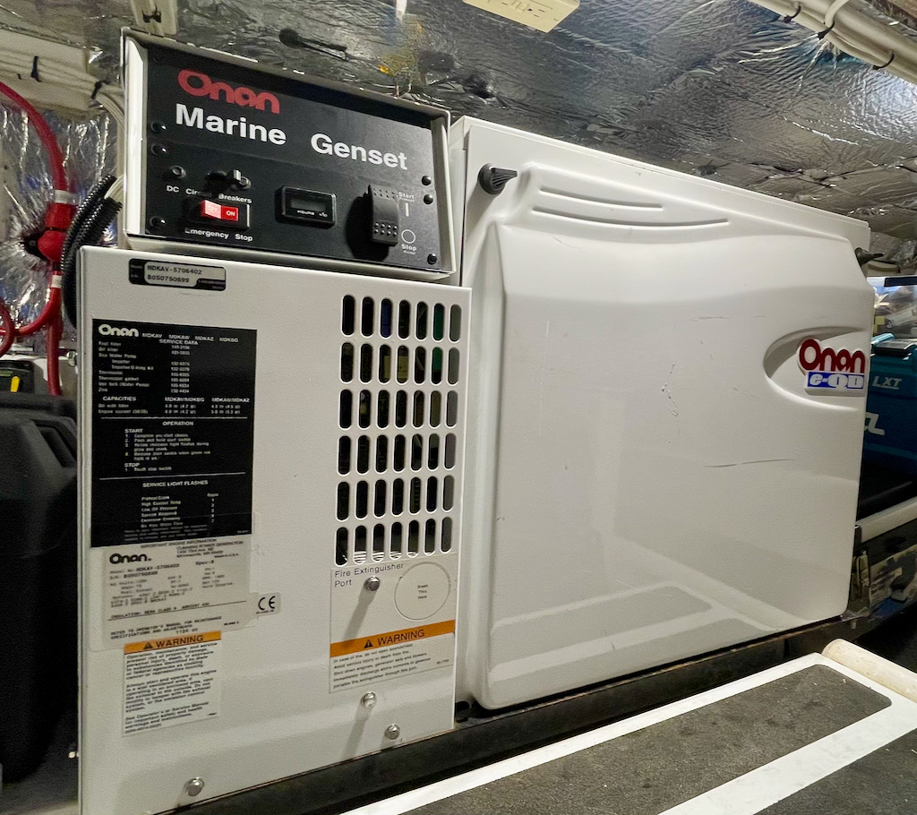
In most boats, the solution to many of the above issues is to install a large generator, and run it a lot. Usually, the generator is the largest available power source, delivering even more than shore power. This is the case with Airship, as our generator is 9kW, and a 30 amp shore power connection can deliver only 3.6kW.
What this leads to is running the generator a LOT – piling on the hours, increasing required maintenance, and burning fuel. It also leads to running the generator most of the time with very small loads, which is bad for the generator engine. All those hours where there isn’t much electrical demand leads to the generator effectively idling, and that causes higher oil consumption, deposits on piston rings, unburned fuel dissolved in the oil, more exhaust smoke, and premature engine failure. Generator manufacturers want us to keep our generators loaded to at least 30% or so, and that leads to many boaters running unneeded electrical loads like space heaters – just to keep the generator loaded up during long runs with otherwise-low electrical demands.
Generators also last longer with fewer start/stop cycles, as each of those causes the equipment to heat up and cool down again, lubrication to start and stop, and so forth – significantly increasing wear. Many boaters – trying to avoid the “lightly loaded” situation described above – end up starting the generator for 10 minutes to make coffee, again for 5 minutes later on to run the microwave, and so forth. This frequent start/stop with short runs also leads to premature generator failure.
We wanted to optimize our generator runtime – preferably running it for fewer hours, under heavier/healthier loads, and fewer start/stop cycles. This should make our generator last longer, burn less fuel, require less maintenance, and should make our experience aboard more pleasant without the constant drone of the generator running. Even though Airship’s generator is relatively quiet, it is not silent.
Build a More Reliable System
Since we really like having power available on our boat, we want to do all we can to improve the reliability and safety of the system. Many aspects of the new system are aimed at that goal. If a battery, inverter, alternator, or even the generator fails while we are out cruising, we want other viable options to keep a good supply of power.
Make the System Easier to Use, Maintain, and Monitor
Boat electrical systems are notoriously fussy, requiring constant attention – lots of flipping of breakers, plugging and unplugging of cables, starting and stopping of generators, load balancing (as discussed above), briefing of guests, maintenance and replacement of batteries, generators, and other components – and, no small amount of head scratching trying to figure out why things aren’t working as expected.
Boat power systems also are usually shrouded in mystery – with many boaters not having the ability to know exactly how much power they have, how much they are using, how much is in batteries, and so forth.
We wanted to reduce that mystery with a system that provided easy-to-understand information about its status and operation – even when we are away from the boat. We want to know how much power is left in our batteries, how long that power will last, how much we are using at any given time, and how much power we are getting from various sources like shore power, generator, solar, and engine alternator.
Major Components of Airship’s New System
We decided to go with an all Victron power system. While electrical gear of different brands generally plays nicely together, there are a number of features that Victron equipment supports that make for a better integrated final solution. Plus, Victron products all come in a very nice shade of blue!
Installation was done by Tony Wyatt at Marine Systems Northwest in La Conner, WA. Tony has installed the electronics on both of our last two boats and does absolutely outstanding work. How outstanding? I (Kevin) am a professional electronics engineer, and we hire Tony to do all of our electrical and electronics installation. An installation this complex is absolutely NOT recommended as a DIY project.
Also, we went with what is called a “hybrid” philosophy for this system. That means we design the system so that all the power we might ever want/need at once (the peak load) can be delivered by the batteries and inverter. This helps achieve a number of the goals above. First and foremost, it means you never are “required” to plug into shore power or run the inverter in order to run anything. No more starting the generator to make coffee or toast. No more waiting until the next shore power to start the laundry.
In a hybrid setup, the role of the traditional power sources is primarily charging the batteries. Shore power, generator, solar, and engine alternator all pump power into the batteries, and the power to run the boat all comes from the batteries (via the inverters for AC loads).
Many of the decisions we made below, especially the size, type, and capacity of batteries and inverters, is to support this “hybrid” setup.
Batteries
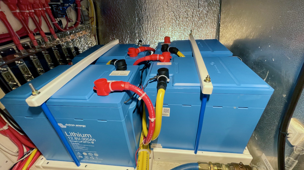
Airship’s new house battery array is made up of four Victron SmartLithium 12.8V 300Ah batteries, connected in parallel. This gives a total capacity of 1,200 Ah, or 15.2 kWh.
These are “Lithium Iron Phosphate” batteries, also called “LiFePO4” or just “LFP”. Now, before you get all up in arms and start the comments about how we’re going to burn the boat down with those “dangerous” lithium batteries, it is important to understand that these are a completely different chemistry than the “Lithium Cobalt” batteries that are somewhat infamous for occasionally catching fire in laptops, cell phones, hoverboards, Teslas, and even Boeing jets. LFP batteries are not a flammable chemistry, are not prone to “thermal runaway”, and are much more stable and durable than those other Lithium formulations.
The tradeoff is that these LFP batteries are less energy-dense (the amount of energy that can be stored in a given size and weight) than their arsonist cousins. In devices like cell phones, energy density is critical – nobody wants to be recharging their cell phone four times per day, or have a phone that’s twice as big just to hold the battery. But, as house batteries on a boat, we are far less concerned with size and weight than we are with safety. In fact, we claim that LFP batteries are safer than conventional lead acid batteries. Lead-acid batteries give off explosive hydrogen gas which, unless properly ventilated, is a serious explosion/fire hazard. There have been countless cases of lead-acid batteries exploding on boats. So far, we have never heard of a properly-installed LFP battery causing an incident on a boat.
Plus, LFP batteries can store about triple the usable capacity of “normal” boat batteries in the same size and weight. Our LFP batteries occupy almost exactly the same space that our previous AGM batteries occupied. The old AGM batteries had a total capacity of 660Ah (7.9kWh), but because AGM batteries should not normally be discharged below 50%, they had a useful capacity of only about 330Ah (3.9kWh). The LFP batteries we replaced them with can be safely used at 100% of their rated capacity without damage, so in the same approximate footprint and weight, we went from 330Ah (3.9kWh usable) to 1,200 Ah (15.2 kWh usable) – almost 4x the usable capacity in the same space and weight. (Ok, 3.9x the capacity if you’re picky about numbers)
Besides 4x the usable capacity, we got a number of other benefits from the LFP batteries. LFP batteries have a much flatter voltage curve than conventional boat batteries (AGMs, flooded lead-acid, etc.) On conventional batteries, as the battery gets lower the voltage drops. AGMs (among the best of those) start at 100% charge with around 12.8 volts. By the time they are down to 50% that has dropped to 12.4 volts, and by the time they are down to 25%, they have fallen to 12.1 volts (all these are assuming no power is being drawn from the batteries when they are measured.) Putting a load on the batteries at any of those levels pulls the voltage down even farther. On a boat, it’s not uncommon to see voltages down in the 11 volt range on AGM batteries that are halfway discharged with a few things still pulling power from them.
LFP, by contrast, have a voltage curve that is extremely stable, with much less drop due to state-of-charge or load. Once LFP batteries are charged to 100%, they will typically show around 13.2V, and they hold that 13.1-13.2 all the way down to around 20% capacity remaining. They also show very little voltage drop even under fairly heavy loads. This makes all your boat appliances – particularly those with DC motors – much happier. It keeps everything running well all the way until the batteries are nearly empty. As a side effect, however, this means you can’t use voltage to tell how full your LFP batteries are. It is important to have a battery monitor that measures the amount of current in and out (along with other factors) in order to get a good “gas gauge” with LFP batteries.
LFP batteries have a much longer lifespan than conventional batteries. Lifespan is measured both in number of full charge/discharge cycles, and also in calendar time. We could analyze for days the numbers claimed by various manufacturers, but the consensus is that they will have something like 5x the lifespan of conventional batteries on a boat. This is good, because LFP batteries are significantly more expensive, so if you’re looking at LFP from a cost-per-year-of-service perspective, it most likely comes out a wash – assuming you plan to keep the boat for a long time. You have to want the other benefits of LFP to make it a sensible investment.
LFP batteries have significant advantages in charging as well. They are much more efficient (meaning that they give back a higher percentage of the energy you put into them) than conventional batteries. Lead-acid batteries are around 85% round-trip efficiency, AGM batteries are much better at about 90% round-trip efficiency, and LFP batteries have over 95% round-trip efficiency. If you’re using a charging source such as solar, this means that much more of the power your solar panels put into the batteries can be used, rather than being lost as heat in the charge/discharge process.
LFP batteries also can accept charge much faster than conventional batteries without damage. Batteries are rated using “C” numbers. The C rating is the maximum charge current as a percentage of the battery’s amp-hour capacity. So, a battery that can be charged at 1C can be fully charged in 1 hour, regardless of size (with a large enough charger). That means a hypothetical 100Ah capacity battery with a 1C charge rating could be charged at up to 100 amps – and would charge in 1 hour. LFP batteries typically have a charge rate of around 1C, while conventional batteries have recommended charge rates of around 0.3C. And, conventional batteries can’t be fully recharged at that rate. At around 85% full, conventional batteries have to be recharged more slowly (absorption), and when they hit about 95%, more slowly still (float). LFP batteries can accept the full charge rate basically all the way until they are full.
Airship’s Victron LFP batteries specify a maximum charge rate of 2C, and a recommended charge rate of 0.5C. Given the size of our battery pack – 1,200 AH – a 0.5 C charge rate would be 600 amps (!!) That means that even with every charging source on the boat working at once, we would not be able to exceed even the recommended charge rate. So, Airship’s batteries will take all the charge current we can throw at them with no fear of damage or overheating.
Finally, by using four 12.8V batteries in parallel, we have a lot of redundancy. If one battery fails, we simply disconnect it at the busbar and the system will go right on working, just with 75% of the previous capacity.
Battery Management System (BMS)
When using lithium batteries, it is critical to have a “battery management system” (BMS) that protects the batteries from overcharging or over-discharging. The idea is pretty simple. When the batteries get above a certain voltage which would indicate they are about to be overcharged, the BMS cuts off all charging sources. When the battery voltage drops too low signaling over-discharging, the BMS disconnects all the loads from the battery. For lithium batteries, it is also critical to never charge when the battery temperature is below freezing, and to never charge or discharge if the batteries become overheated. So, the BMS should have a way to detect battery temperature and disconnect charging sources and loads as appropriate.
It is important to understand that in normal use, the BMS should do nothing. We want all our chargers to be “smart” and to automatically stop charging when the batteries approach “full”. We also want to design the system so there is little chance of ever over-discharging batteries. And, we don’t want to ever have the batteries below freezing anyway because below-freezing temperatures in the engine room are bad for other reasons. But the BMS is there as the final protection to save the batteries if something goes wrong elsewhere in the system.
Many lithium batteries (sold as “drop in” replacements for conventional batteries) have the BMS built into the battery itself. This has obvious advantages in simplifying system design, but some disadvantages as well. In many cases, the built-in BMS limits the amount of charge or discharge current, even though the battery cells themselves could handle much more. And, if the built-in BMS fails, it effectively takes out the battery as well.
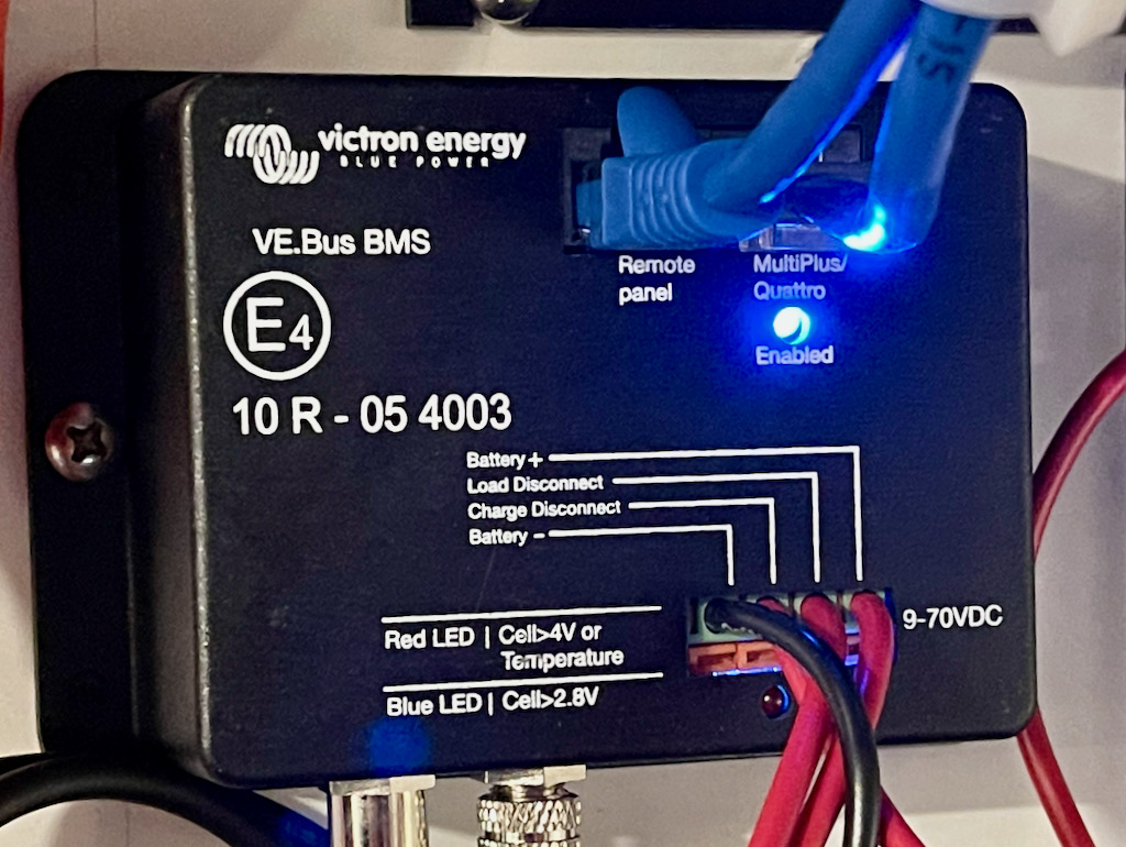
Instead, we chose Victron SmartLithium batteries, which depend on an external BMS. We got the Victron Ve.Bus BMS, which communicates directly with the batteries and all the other components of the Victron system (chargers, load disconnect units, battery combiners) to turn the loads and charging sources on and off. No actual current flows through this type of BMS. It simply monitors the system and controls the attached components, so it doesn’t have to be sized for any particular (large, in our case) current demands.
While the BMS can talk to all the Victron components just fine, it can’t communicate with the non-Victron stuff in the boat, such as the engine alternator and the DC distribution/breaker panels. Since we want the BMS to be able to shut off all the DC loads on the house batteries, we use a Victron BatteryProtect, which can, on command from the BMS, shut off all current from the house batteries to the DC distribution panel.
Also, with lithium batteries, it is important to periodically “balance” the cells. All types of batteries used in boats are really made up of multiple lower-voltage cells connected in series to give the correct total voltage. For conventional lead-acid batteries, each cell is 2 volts (yep, that’s why there are six water-fill caps on top of old, non-sealed flooded lead acid batteries.) Those six cells are connected in series to make a 12 volt battery. Lithium batteries are made up of cells with a nominal voltage of 3.2 volts each, and four cells are connected in series to make a 12.8 volt battery.
Over time, on all types of batteries, those cells go out of balance. One cell may start to get weak, and charge to a lower voltage. But, the battery charger wants to charge the whole pack to a specific voltage, so it ends up over-charging the other cells to compensate for the weak cell in the series. This gradually gets worse and worse with the result that the pack fails from overcharging the strong cells and undercharging the weak ones.
Lithium batteries are almost always set up with automatic cell balancing. Once the whole pack is up to a specific voltage, the balancing circuits kick in and bleed current away from the “full” ones while continuing to bring the “slow” cells up to the correct voltage. This keeps the whole pack in balance and gives much longer life than if the cells were allowed to gradually stray out of balance. The Victron batteries we chose have built-in balancing, and the cells are automatically balanced any time the overall voltage is held over 14 volts. Victron recommends an “absorb” time of 2 hours at 14.2 volts at least once per month to maintain balancing.
This brings up another major difference between lithium and conventional batteries, though. Conventional lead-acid batteries like to be regularly charged to 100% capacity, and last the longest when held at or near a full charge. That means you need to regularly run chargers/generators/etc – to top off the batteries, and occasionally even over-charge them in a process called “equalizing” by holding them at a very high voltage for a few hours to remove sulfate crystals that accumulate on the battery plates.
Lithium batteries, on the other hand, are happiest about half charged. This is why when you get a new device with lithium batteries built in, it almost always arrives with the batteries half charged – that is the best “long term storage” state for lithium cells. So, when used as house batteries, there is no need to keep lithium at 100%. In fact, it’s bad for them. Aside from the once-per-month balancing charge, it’s preferable to keep lithium in the 20% to 80% range for the longest life. We set up our charging profiles to approximate this. Also, when using the generator to recharge, we tend to stop when the batteries get to 80-90% rather than taking them all the way to full.
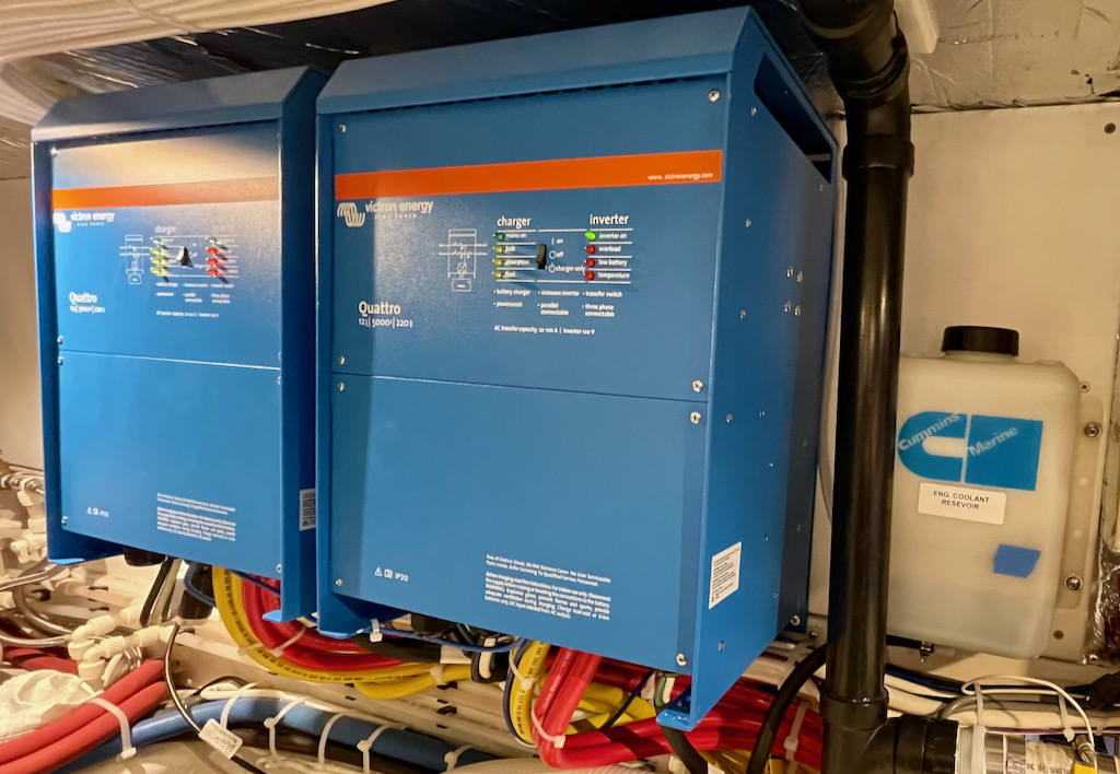
Inverter/Chargers
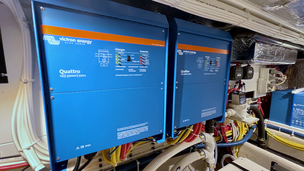
We installed two Victron Quattro 5kVA 12/120V inverters (wired in parallel) on Airship.
This gives us what most would consider an absurd amount of inverter capacity. But, remember that our “hybrid” philosophy is to have the inverter capacity to run all the loads we might want to run at one time – all from the inverters. 10kVA works out to about 8kW (rather than 10kW, because of “power factor” which we won’t bother to discuss here). So, with this dual-inverter setup we can run basically anything we’d be able to run with our 9kW generator.
The dual inverters are one of the compromises we had to accept in order to get that capacity without switching from a 12V to a 24V DC system. 5kVA is the largest 12V inverter Victron makes, but they have much larger units available at 24V. The reason is the enormous DC currents required to produce 8kW from inverters, and the huge wires required to safely deliver that current from the batteries to the inverters.
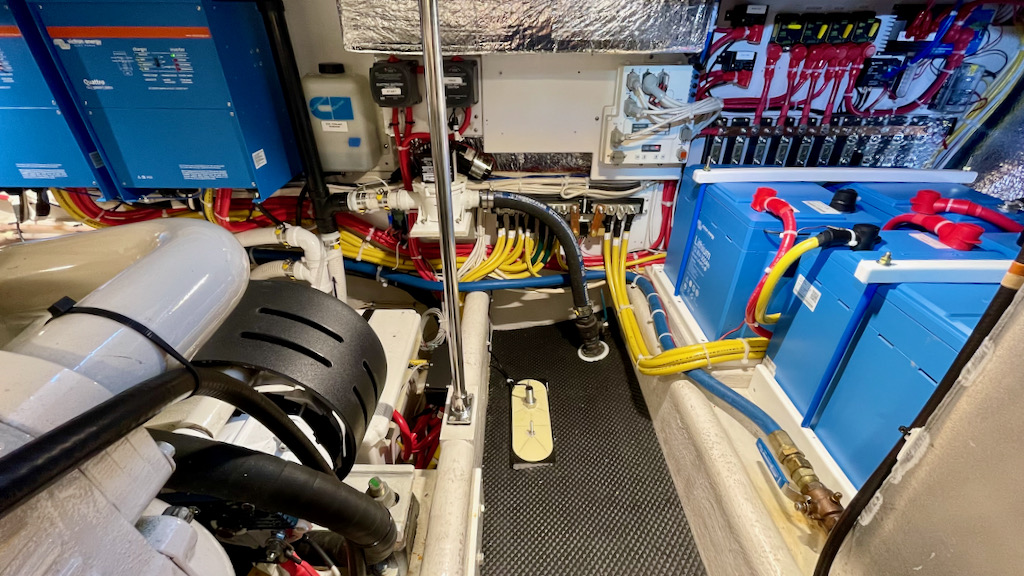
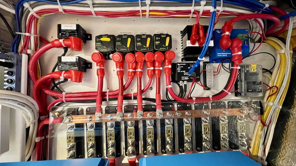
If these inverters were operating near their 10kVA total capacity, something in the neighborhood of 1,000 amps of DC supply would be required. In order to handle that current load, each inverter is fed by two parallel 4/0 cables for the positive, and two more for the negative. That makes eight of the largest-gauge wires you can get running between our batteries and inverters, complete with appropriate fuses and busbars. In addition, to balance the operation and demand on both the inverters and batteries, those wires and busbars have to be installed so that the round-trip length/resistance is the same for all four paths – from battery terminal through positive path to inverters, and back again to negative battery terminal.
In a 24 volt system, the currents are cut in half for the same total power output, and therefore the demands on wiring would be halved as well. So, because we wanted to stay with 12 volts, we had a massive wiring challenge between the inverters and batteries. Tony designed a beautiful DC distribution system.
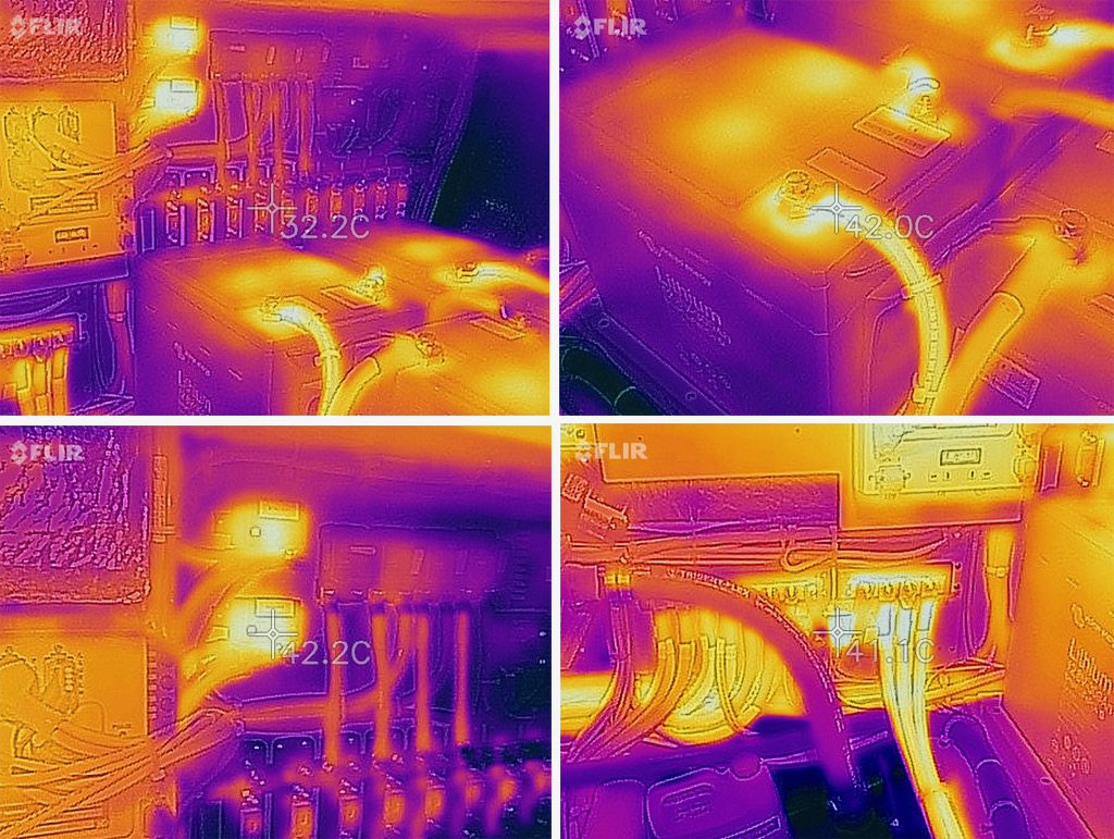
As you can see from these FLIR thermal photos with the system operating at a stress test charge of over 400 amps for a couple of hours, the wiring worked beautifully and there are no significant hotspots or imbalances. That means in normal day-to-day operation, everything will be cool, stable, and safe – regardless of the demands we put on the electrical system.
These Victron inverters have another feature we wanted – called “PowerAssist”. Since Airship has dual 30A shore power connections, we usually connect to only one 30A connection when we are staying for a short time at a marina. 30A is plenty to run a normal day on the boat (unless we are constantly running electric heaters and electric water heat). But, occasionally, if someone runs a hair dryer at the same time the electric water heater is on, and someone else makes a shot of espresso… BOOM. We trip the 30A breaker. 30A is about 3,600 watts. Take a 1,500 Watt water heater, an 1,800 Watt hair dryer, and a 1,000 Watt espresso maker – and you blew it. But, these overages are usually fleeting, you run the hair dryer for three minutes and you’re done. Shot of espresso? One minute max.
What PowerAssist does is monitor how much you are pulling from 30A shore power. If you start to get close to the limit, and the inverter/chargers are charging house batteries, it reduces the charging power in order to stay under the 30A limit. But, if charging power is already at zero and you are in the above scenario, the Victron inverter/chargers switch from “charge” to “invert” and use some power from the batteries to supplement shore power and avoid kicking the breaker. We tried this by putting about 5kW of loads while on 30A shore power. Sure enough, the charger stopped charging, and the inverter started boosting the power … and the 30A shore power breaker did not trip – even though the boat was using the equivalent of more than 40A. The net result? Just hook up 30A shore power and forget about it. Run whatever appliances you want. We should never trip a shore power breaker again.
We did, however, run into a couple of “gotchas” related to this feature, which we will explain in the issues section below.
The reason we went with Victron Quattro units (rather than Multi-Plus) is that Quattro have separate AC inputs for shore power versus generator. Since our generator can output up to 75A AC, and shore power is often 30A or less, we didn’t want to have to re-configure the system every time we went from shore power to generator (in order to make PowerAssist work correctly, among other things). The Quattro allows separate settings for the 2 inputs and automatically switches back and forth depending on where available power is detected.
Solar
Many people debate whether or not solar on a boat is worth it. Truly, if you spend any time off the grid at all, solar is most definitely worth it. Solar is silent, virtually maintenance-free, and dramatically extends the amount of power you can get from your house batteries. Think of solar as a free battery charger that runs for several hours per day automatically. And, while the output of solar panels may seem like a drop in the bucket compared with cruising boat demands, in summer it is possible to just about 100% power your boat with solar here in the Pacific Northwest (which, by the way, is not famous for sunshine).
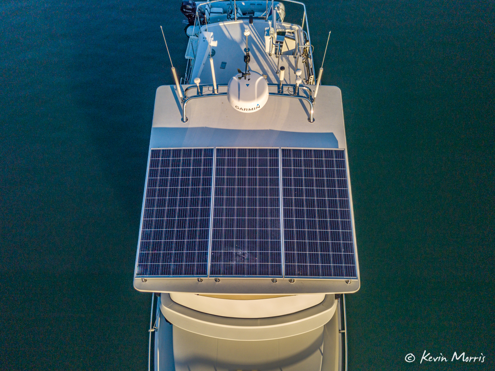
Since we upgraded to a fiberglass hardtop over the flybridge (replacing the old canvas bimini), we have an ideal, non-shaded place to plop down some serious solar. We are often asked what is the “ideal” amount of solar to put on a boat, and there are all kinds of silly formulas and theories about balancing batteries and usage and… just no. The correct amount of solar to put on a boat is – as much as you can possibly fit. You simply can’t have “enough”. And panels are cheap and easy to install compared with just about any other boat-related system.
The limiting factor on solar is available roof space without partial shading. And, it is critical that you locate panels in a place that has no partial shading. Because of the way solar panels work, even a small amount of shade severely reduces the amount of power you get. Shade on as little as 5% of the panel can drop the output of the panel by as much as 80%. You’re ahead to have a smaller panel that isn’t partially shaded rather than a large panel with a chunk that is regularly shaded. And, while most panels have “bypass diodes” that help with the problem, the only real solution is to try to put panels in a location where there is no regular shade.
On Airship, without the hardtop, there was approximately zero usable space for solar panels. But, with the hardtop, we located all those nasty shading antennas and radar domes as far back as possible, leaving a nice wide area for solar panels with minimal shade possibilities. We chose the highest total output we could fit in the area – which was three 380W panels made by Silfab solar. We liked supporting Silfab as a local company, and their panels have a very good reputation. They are available in the small quantities we use on boats (rather than only in the large quantities for home and industrial use as with many manufacturers). And, most importantly, they allowed the most output in the dimensions we had available for panels.
It is easy to get lost in the data for solar panels, and people get very deep into mono- vs poly- silicon, cell efficiency, and a number of other factors. The thing is, the best cells in the world may be in a panel whose dimensions only allow you to mount one or two, where a lower-efficiency panel may be sized to allow you to fit three, and get more total power. There is no single right answer, as each boat presents a bit of a puzzle to solve with panel dimensions, output ratings, partial shade, and so forth. Our solution gave us a total power rating of 1,140 watts, with almost no partial shade (except when the sun is coming from very low astern).
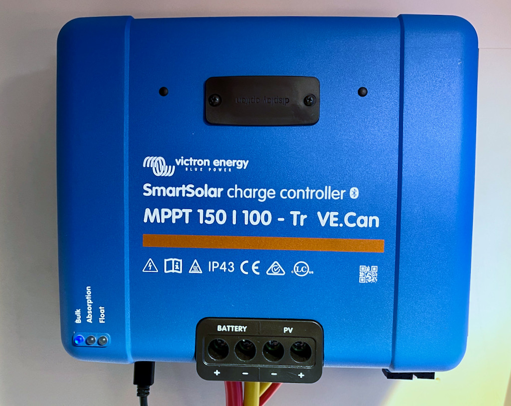
We connected the three panels in parallel, (which is almost always the best solution on a boat), and used a Victron 150/100 MPPT charge controller to connect them to our system. On a boat, always use an MPPT solar controller (not a PWM). The MPPT allows the solar panels to operate at their most efficient voltage and current, and converts that on the other side to the correct voltage and current for charging your batteries. MPPT are MUCH more efficient than PWM controllers, so more of that solar capacity you struggled to achieve makes it into your batteries. This also means you do not need to try to buy (for example) 12V panels to charge 12V batteries. Our panels, for example, have 72 cells each and maximum power output is at about 39 volts. Our batteries need to be charged at about 14.2 volts. The MPPT controller lets the solar panels run at max output at 39 volts and around 30 amps total (all three panels), and converts that to 14 volts at 84 amps each to charge our batteries. The higher voltage and lower current means we can run much smaller wires from the panels to the controller without losing as much power in the wiring.
The two specs on the MPPT controller (150/100 for ours) are the maximum voltage and current the controller can handle – up to 150 volts from the panels in our case, at up to 100 amps output on the charging side. The open-circuit (maximum) voltage on our panels is 48V, so we could have chosen to connect them in series (giving 144V) or in parallel (giving 48V). Series is more efficient in terms of wire losses, but is terrible if you have any partial shading at all. Parallel has slightly more loss from wiring and requires larger wires, but gives much more immunity from partial shade. Hence, we decided to go with parallel.
We had a brief chance in summer to see how our solar system performed after the solar panels were installed, but before the Lithium batteries, inverters, and so forth were installed. For a couple of days, we saw somewhere in the range of 10 kWh per day of output. We don’t have enough data to know if this is true, but if so, in summer, solar will be able to supply 100% of our normal off-grid power demand (we currently estimate we use about 7kWh per day off grid.) Winter is a different story, however. We now have extensive data on winter use, and we see that on a typical heavy-overcast, short fall/winter day we get slightly over 1kWh per day from the solar, and on the rare “sunny” (but still short) fall/winter day we get a little more than 2kWh. So, in the winter, we still need a daily generator run if we’re staying in one location and not getting some battery charging from the engine alternator.
Engine Alternator
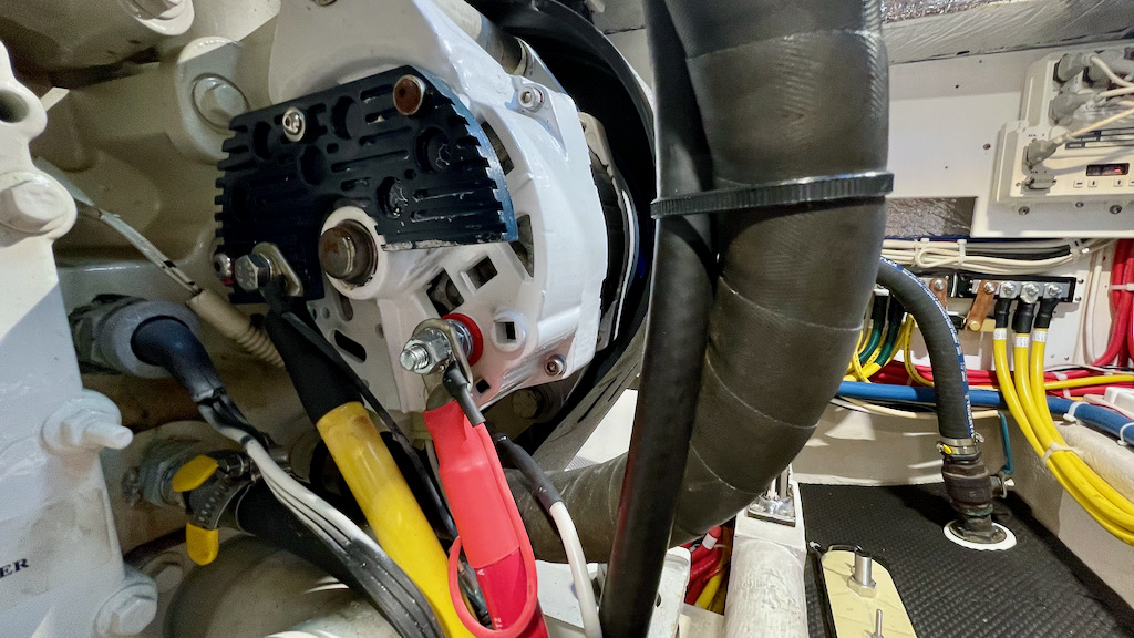
While this upgrade was actually done the previous summer, we were already anticipating upgrading the rest of our power system when we replaced the stock alternator on our Cummins QSC 8.3 540HP diesel engine with a heavy-duty 210 amp Balmar alternator with a Balmar MC-614 external regulator.
If you have a big house battery array, and particularly if you are contemplating upgrading to lithium batteries, the stock alternators that come with these engines absolutely will not cut it. Those alternators were designed for use in trucks and heavy equipment. In that world, the engine starter puts a big-but-short heavy load on the battery. After that, the batteries don’t have that much to do. The job of the engine alternator in that scenario is to push out a bunch of current quickly in order to replace what was used starting the engine, and then to keep the battery topped off while running much smaller loads on the truck.
So, if a stock alternator is “rated” at 150 amps, read the fine print. Most likely it is able to put out 150 amps for a few seconds. After that, if it still has a heavy load, it will overheat and begin to self-destruct. If you are using your alternator to charge your house batteries, it can easily be at max output for hours. Unfortunately, with a normal internally regulated alternator, there is no way to prevent this. The alternator does not know it is overheating, and it will quietly work itself into an early grave. Smell something like burning cedar underway? That’s the windings in your alternator slowly roasting off their insulation and your alternator diodes preparing for their untimely demise.
Lithium batteries make this problem MUCH worse. Lithium batteries will take about as much charge as you can give them, and their siren song will lure any ordinary alternator into oblivion. Heavy-duty, externally regulated alternators such as the Balmar we installed give higher output, are rated to deliver that higher output much longer, have much improved cooling, and have temperature sensors that allow them to be backed off if the regulator senses they are getting too hot. In addition, the external regulator allows you to program in complex battery charging programs for any type of battery. (More on this later in the issues section).
Charging Multiple Battery Sets
When we are underway, we want the alternator to charge the engine start battery, but also the house batteries, and the bow thruster/windlass batteries. Since the house batteries are now lithium, but the engine and windlass/thruster batteries are lead-acid, they have different charging requirements. Further, we want those batteries to be normally disconnected from each other, so the engine will start and the windlass will still run well, even if the house batteries are down.
There are a number of ways of achieving this isolation and multi-battery charging. The old-school way is a battery isolator, which uses diodes to allow a single charger to charge isolated batteries that may be at different voltages. The downside of the diode approach is that a diode forces a 0.7 volt drop. So, whatever voltage your charger is putting out, the batteries on the other side of the isolator will see 0.7V less. A second solution is to use a DC-to-DC charger. This would allow a DC battery and charger on, for example, the engine start battery to charge the lithium house batteries, and would maintain the proper charging profile for the batteries being charged. The downside of the DC-to-DC charger is that it is one way only.
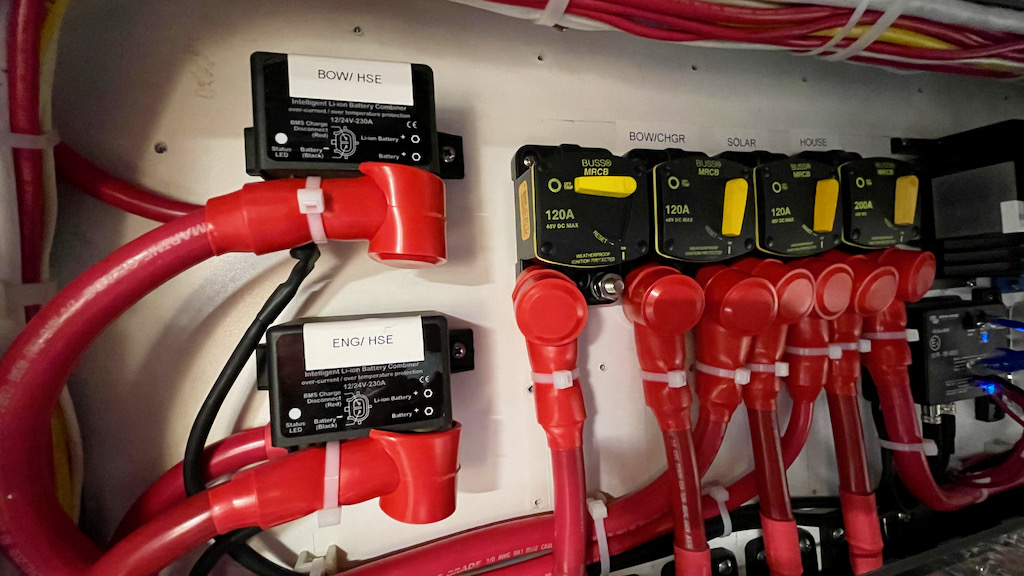
But, we want two-way charging. If the generator or shore power is charging the house batteries through the Inverter/Chargers, or if solar is charging the house batteries, we want the house battery side to be also charging the engine and windlass batteries. But, if the alternator is charging the engine battery, we want the charge to go the other way – from there to the house and windlass batteries. For this reason, we chose an automatic charging relay (ACR), the Victron Cyrix, to handle the job. The Cyrix automatically either combines or disconnects two batteries based on a set of pre-programmed rules. When it detects that one battery or the other is being charged, it connects the batteries together so they are both charged at the same time. When it detects that the charging has stopped, it disconnects the two batteries so they are once again isolated.
This process seems straightforward enough, right? It doesn’t have the voltage drop of diodes, it allows two-way charging so all the batteries can be charged by the alternator, solar, generator, or shore power… but, it turns out there are some “gotchas” which we will discuss in the issues section.
There are several Cyrix units available at various current capacities, and a special one for lithium batteries that has different voltage triggers. We got the 230 amp Cyrix-Li-Ct to connect between the lithium house batteries and the engine start battery. Our engine alternator is connected directly to the engine start batteries, then to the house batteries through this Cyrix. When the engine is running and the alternator is charging, the house batteries could allow a large amount of charging current, so we needed a combiner that could handle the full capacity of the Balmar alternator in that direction (210 A maximum). When the charge is going the other direction – from the house battery side (shore, generator, and solar) to the engine start batteries, the amount of current that the engine start batteries could take is much smaller.
For the windlass/thruster batteries, the charge is much smaller, and always one direction (there are no charging sources attached directly to those batteries), but we went with the same type of combiner just to keep things simple.
AC Panel Rewiring
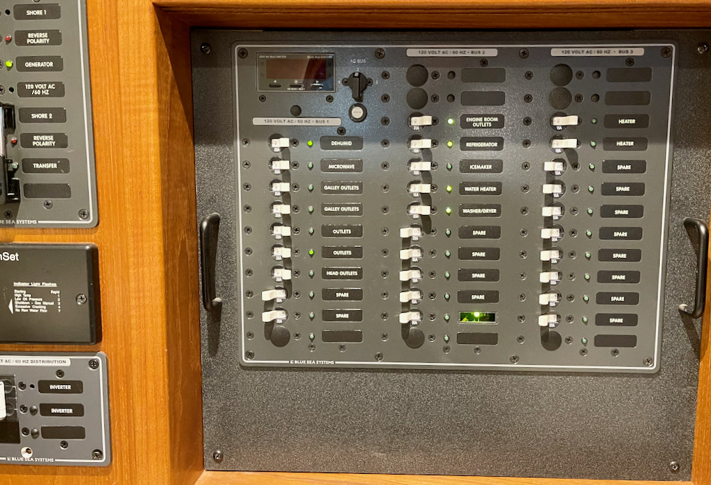
Because the Quattros have the PowerAssist feature, the boat’s AC wiring has to be done differently. In a normal setup, the shore power and generator connections go to the AC distribution panel via a transfer switch that lets us select “shore” or “generator” to the panel, and then the inverter/charger is powered from a breaker off that main panel. Then, a limited set of loads are on a separate AC bus that can be driven by the inverter when it is active, and that passes through that shore/generator current when the inverter is not active.
With the Quattro, both the shore power and the generator output are wired through appropriate breakers to the Quattro inputs. The output of the Quattro then goes (through more breakers) to the AC distribution panel. The Quattro then becomes the transfer switch that supplies the panel with generator, shore, or inverter power, and enables the PowerBoost feature to supplement shore/generator with inverter power for large peak loads.
This is generally a cleaner, more straightforward setup, but it brings a few caveats. First, if your inverter/charger overheats and disables the pass-through connection, even your generator and shore power cannot get power to the AC distribution panel. This should be a very rare occurrence, but we have heard of it happening on boats with large loads and undersized inverter/chargers operating in warm climates. It resolves itself when the inverter cools and the thermal protection shuts off, or you can install a bypass wiring system that lets you go around the inverter in case of emergency. Since our inverters are oversized and therefore far less likely to overheat, and since we have 2 inverters giving us some backup as well, we chose not to wire a backup. In the event of a complete dual-inverter failure, we could manually move a wire and be back in business.
PowerAssist does bring in a sneaky new risk, though. If the boat is plugged in long-term in a marina, and the marina power fails, the inverter will step up and power the boat… until the batteries are dead and the BMS disables the loads to protect them. One easy solution to this is to switch the inverter/chargers to “charge only” when the boat is stored, so that the inverter will not try to power the boat if shore power fails.
Taking that issue one step farther, though, the biggest loads in our boat tend to be things like electric heat and electric water heat that are almost exclusively used when plugged into shore power. In the winter in a marina, those items can run for hours on end. And, it is easy for just a couple of electric heaters plus the water heater to exceed 30 amp shore power. So, with PowerAssist, it is still possible that the boat would just be using more than 30A shore power can provide over the long haul in those circumstances, and gradually draining the batteries to try to keep up.
Luckily, Airship came from the factory with dual 30 amp shore connections. The second 30A connection goes to a separate bus on the AC panel, but goes through a transfer switch so that separate bus can be powered either by the second 30 amp shore connection, or paralleled to the rest of the panel so it’s powered by the first 30 amp connection, generator, or inverter. So, we moved the electric heat and electric water heater to that separate bus, taking care to keep below 30 amps even when everything on that bus is active at the same time.
This allows us to plug in the second 30A shore cable when in a marina with 50A 240 power, or dual 30A power available (mainly for long-term storage) and leave the electric heaters and water heater on to maintain some minimum temperatures, and leave the inverter active on the main bus with the main shore power connection to keep the refrigerator and a couple other loads operating. If there is a power failure, the bus with the big loads (heaters, and water heater) will disconnect, but the inverter/batteries will keep the things like the refrigerator on the main bus running indefinitely assuming we have at least some solar power coming in.
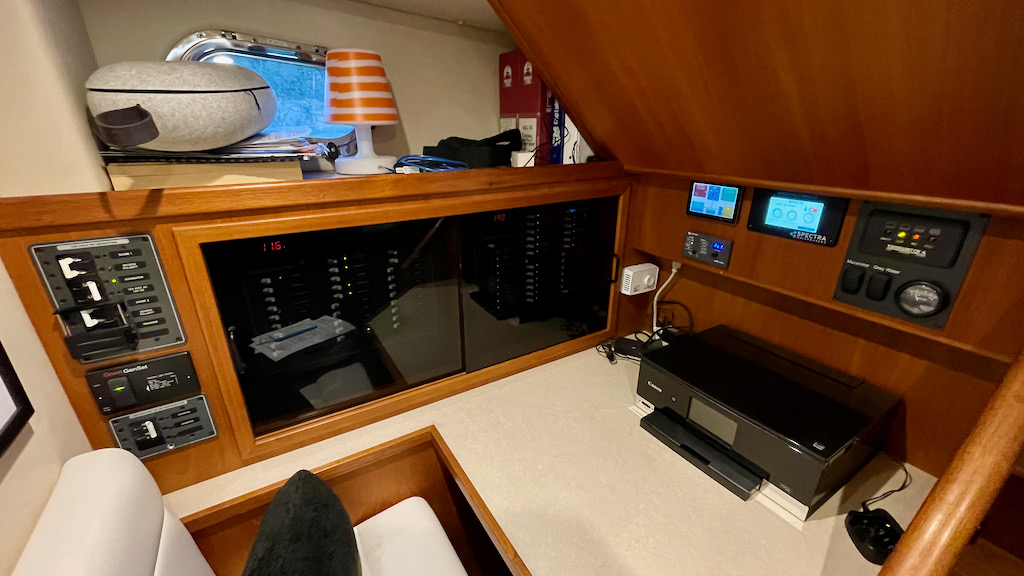
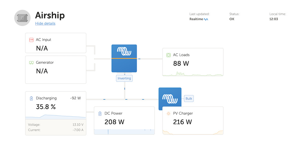
Monitoring
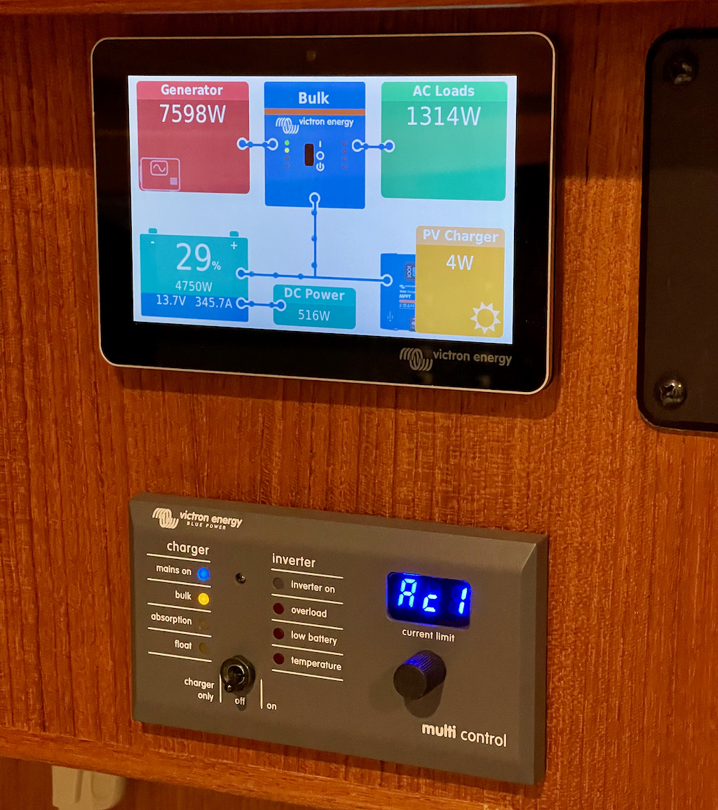
The Victron system really shines when it comes to monitoring. For central control/monitoring we installed the new Cerbo GX along with the compatible touch screen. The touch screen is a little larger than a cell phone, is easy to mount, and gives easy at-a-glance display of the entire system operation as well as control of most of the relevant settings on the components. It also has both bluetooth and Wifi connections so that any device (smartphone, tablet, laptop) can connect and monitor and control the system. If your boat has full-time internet connectivity, you can have it upload the data to Victron’s cloud server, which allows you to monitor and control the system remotely from anywhere. I’m sitting at home right now 250 miles from the boat, and can see what the batteries, inverters, shore power, solar, and all the loads are doing in real time. I could even reprogram the inverters from here if I wanted to for some reason.
There are many more cool features of the Cerbo which we won’t go into here, but it’s great for peace of mind to be able to check on the boat any time from anywhere.
Issues
While the goal of this system was simplicity – we wanted electrical power to just “be there” like at home, rather than being fussy and requiring constant attention and management – that operational simplicity requires a very complex installation. We have massive DC current-carrying wiring, countless fuses and other circuit protection and switching. Parallel inverter/chargers that require balanced-resistance, matched-length cabling, BMS that must communicate with the whole system via data cables, safety issues, just fitting all the equipment into the available engine room space (that was a biggie, it turns out), the list goes on and on.
Of course with all that, we ran into a number of issues that it pays to discuss below.
Parallel Inverter Issues
Putting two inverters in parallel sounds simple enough: just put matching AC and DC wires to and from each inverter. But arranging the system so that all the paths were identical resistance from the positive of each battery through all the fuses and busbars to the inverter, and then back through the negative path, is a crazy challenge. Luckily Tony was up to the challenge and, as our thermal images showed, we are seeing nearly identical temperatures on all paths at high current loads – indicating that the system is nicely balanced.
One might think that having two inverter/chargers would provide an easy fail-safe. If one unit fails, you still have the other one to fall back on. But, that’s not as simple as it sounds. Once you program the Victron units to operate in parallel, they REQUIRE the other unit(s) to be present and active. If you lose one inverter, the other one simply gives an error and won’t start up. In the event of a failure, we’ll have to switch off the bad inverter, possibly disconnect some wires, and re-program the remaining inverter for stand-alone mode. Honestly, we don’t have a checklist for this process yet, so we’ll need to come up with one in the future. For now, suffice to say it’s a lot more complicated than it seems it should be.
Earlier we mentioned the wonderful PowerAssist feature that boosts shore power temporarily if the boat asks for more power than is available from the shore power connection. In order for that to work, the inverters have to know how much shore power is available so they can reduce battery charging and eventually switch into inverter/boost mode as the loads approach the limit. From the factory, however, the lowest setting the Quattro inverters would allow is 19 amps… EACH. That means the total lowest setting for the system was 38 amps – which is completely useless when dealing with 30A shore power. As a result, when we powered up the system, it started charging the batteries and running other loads and … almost immediately tripped the shore power breaker. PowerAssist would not kick in until we hit 38 amps, and the breaker would trip at just 30. Luckily, Victron had a firmware update which allowed each inverter to be set as low as 13 amps – for a total of 26. That is just enough to allow proper operation on a 30A shore connection, with a little bit of extra if we are at a marina that has 30A connections, but an old breaker that trips a little lower than that. It did require a firmware update on the Quattros, which was a bit of a hassle involving laptops and dongles and ethernet cables and… you get the idea.
Alternator Charging Issues
It turns out there were some bad interactions between the Cyrix-Li combiner and the Balmar external battery regulator. To review – the Cyrix connects the engine start battery and house batteries together when it detects either is actively being charged, and then disconnects them when charging ends. In addition, once charging has begun, it wants to be sure that a big load on one battery doesn’t pull down the other one.
So, for example, if you had a small alternator putting out maybe 50 amps, but the house batteries had a 100 amp load, both engine AND house batteries would be discharging even though the alternator was helping out. This could eventually result in dead engine batteries that won’t start the engine. So, if (while charging) either side of the Cyrix drops below 13.2 volts, the Cyrix disconnects in order to avoid this condition. Makes sense, right?
Now, looking at the Balmar side of things… The Balmar alternator regulator conveniently has a charging profile specifically for lithium batteries. It begins with 18 minutes or so of “bulk” charging where the full output of the alternator is sent to the batteries without question. It then goes into a longer period of “calculated bulk” charging where it is basically deciding whether to continue bulk charge or to move on to the next phase “absorption”. In order to do this, it periodically stops charging and monitors the voltage to see if it’s time to switch to absorption. If the voltage drops rapidly, it continues bulk charging. If the voltage drops more slowly, it moves on to absorption.
It is during this “calculated” period that our troubles started. After about 18 minutes underway, when the Balmar went into “calculated” mode and stopped charging temporarily to monitor the voltage… The Cyrix says “Hey, the house battery voltage just dropped below 13.2 volts, we need to protect the engine batteries from discharge, we are OUT! And, unceremoniously disconnected the house batteries from the engine/alternator. And, that was it for the alternator charging house batteries on that trip. The alternator kept charging the engine batteries, and the house batteries with some load on them and no charger working remained below 13.2 volts, so the Cyrix never had a reason to reconsider its “disconnect” decision. Bah!
The fix for this issue was to reprogram the Balmar to remain in “bulk” mode for a long time (we just chose the maximum – six hours) before going into the “calculated” mode. And, we set the “bulk” voltage to 14.2 volts – which is the best charge/balance voltage for our batteries. So, we basically took this fancy, expensive multi-mode external alternator regulator and turned it into a fixed-voltage type like you’d find in any 1970s-era automobile regulator. (Except this one has critical over-temperature protection).
After further consideration and some back-of-the-envelope math, it turns out that the fancy multi-stage charging capability isn’t really useful for alternator charging in a system as large as ours. If we assume we use half of our battery capacity overnight at anchor… we might start a cruising day with the batteries down by 600 Ah (8kWh). If the alternator is managing to put 100 amps into the house batteries while underway (in addition to recharging the engine start and windlass batteries and running all the boat loads), we would need to be underway six hours before the regulator would need to switch from “bulk” to “absorb”. And, Victron recommends a two hour “absorb” period at 14.2 volts in order to balance the cells. So, we could be underway for eight hours with the alternator flat-out at 14.2 volts before we would want anything besides a steady 14.2V.
It is rare that we cruise for more than eight hours in one stretch. Even if we do, there is no harm in holding the batteries at a steady 14.2 volts for longer. If it went on for days and days, it isn’t the best for the lithium batteries, but even then it won’t do any serious damage. So, it turns out that in practical terms, the fancy Bulk-Absorption-Float programming on the external regulator doesn’t really come into play with a large battery array. We really just need a fixed voltage, temperature protection for the alternator, and the largest alternator that can sustain a heavy current load for a long period of time.
Generator Charging Issues
In general, the generator charging works spectacularly well with this system. If we reach the end of the day at anchor and the batteries are down in the 20-40% range, we will run the generator to recharge them. The two Quattro inverter/chargers can do a whopping 220 amps each in battery charger mode, so we can run the generator and be putting about 400 amps back into the batteries. If the batteries are down to 20%, that means we have taken about 960 Ah out of the batteries. If we run the generator for two hours, dumping 400 amps into the batteries, we put back 800 Ah, running the batteries up to a happy 87% or so. Also, this puts a load of over 5kW on our 9kW generator (plus any house loads running at the time) so we have no issue with the generator being under-loaded.
This accomplishes our “be kind to the generator” goals spectacularly well, as we can get by even with extended off-grid time in the winter with running the generator one time per day, for two hours or less, keeping it nicely loaded the entire time. And, we can still use power basically without limit.
The only “gotcha” we experienced with generator charging was due to the breaker installed on the generator at the factory. Even though the generator is rated at 75 amps AC, the breaker on it was 70 amps. We had based our PowerAssist and charging settings on 75 amps, so the generator was kicking the breaker on the unit itself. We chose to resolve that by reducing the settings on the Victron gear for 70 amps max, rather than taking the risk of putting a larger breaker than the factory installed on the generator.
How Well Does it Work?
Our cruising habits vary significantly between summer and winter cruising seasons.
In summer, we typically cruise for several hours each day, and stay at a new anchorage almost every night. We (almost) never need to run the hydronic heater. The daylight hours are long (particularly when we are in SE Alaska) and the angle of the sun is high.
In winter, we tend to stay at a single anchorage for several days in a row. We are often in the San Juan Islands, so the cruising distances are short when we move. The daylight hours are short, and we run hydronic heat most of the time.
This means the electrical system faces completely different scenarios in the two seasons. Long cruising stretches (summer) mean the alternator is charging batteries for many hours each day. Short stretches and repeated days at the same anchorage (winter) means the alternator doesn’t contribute much to charging, and we need to rely on other power sources more.
Long days of sunlight (summer) will allow solar to provide a significant chunk of the energy (perhaps 100%, but we shall see). Our limited testing in summer showed that Airship’s new solar system pumped out as much as 10kWh per day, which would be more than our average daily power use. Short, often overcast days in winter mean solar will make very little contribution – a little over 1kWh per day average, with less on cloudy days, and closer to 2kWh on the short, sunny days with the sun at a low winter angle. That (potential) 10x difference in summer/winter solar output is a dominant factor in the difference between summer and winter.
On the demand side, one wild card is the need for electric water heat. When we use it, electric water heat is the single biggest energy user on our boat. Our water heater heats from 3 sources – engine heat, hydronic heat, and electric. It heats the water in the (11 gallon) tank to a much higher temperature than what we need – up to 167F. It then has a thermostatic mixer at the exit of the water heater that mixes the super-hot water from the tank with cold water to achieve our normal “hot water” temperature. This has 2 advantages – the hotter tank water lasts longer with no heating sources active. And, mixing the “super hot” water with cold water for our actual supply makes it work as if we had a much larger hot water tank.

When we are underway, the engine heats the tank up to engine temperatures (around 160F). In winter, when we run the diesel hydronic heater, it keeps the hot water to about the same temperature. When we are in a marina on shore power, we run the electric water heat (since the other two heat sources are not available). In winter, we have found we do not need to run electric at all when away from the marina. The hydronic heat keeps our water hot all the time. In summer, without the hydronic, we expect engine heat during cruising will give us enough hot water to make an overnight until cruising the next day. If we stay at an anchorage more than one night, we will almost certainly need to use electric heat to maintain hot water. That means our total power use will be much higher (maybe double?) on subsequent-day stays at a single anchorage in summer.
All these factors boil down to how much the generator (and/or shore power) are needed in summer vs winter. Our expectation (we will report this summer) is that we may not need to run the generator at all for normal use in summer, with the only exception being maintaining hot water on multi-night summer stays in a single anchorage. It is possible, though, that solar in summer may still be able to handle even that load without running the generator. We shall see.
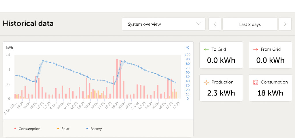
Less solar, less alternator, and longer stays at anchorages in winter mean we most definitely need the generator. Our daily usage in winter seems to be about 8kWh per day. Solar provides an average of 1kWh of that, so that leaves 7kWh to be provided by the generator.
The system works spectacularly well for this. With the 2 Quattros able to charge at up to 400 amps, we see a real-world output of 380 amps or so when running the generator to recharge batteries. That works out to over 5kW going into the batteries when the generator is running. So, supplying that 7kWh daily power to run the boat in winter requires less than 2 hours of generator run per day. We just start the generator up in late afternoon/early evening, run it for 1.5 hours or so, and shut it off. During that run, the generator is 80% or so loaded – we have nailed our “be kind to the generator” requirement, and as a bonus we have a nice, quiet, generator-free boat 22.5 hours per day, while using all the power we want.
With the huge capacity of the dual Quattros, as well as the generous capacity of the lithium batteries, we also achieved the “eliminate the need for load balancing” as well as the “make more power available” and the “ease of use” goals. We run any and every electric load and appliance on the boat, whenever we want, without giving it a second thought.
When we are in a marina long term with 50A power available, we switch to electric heat for the boat and hot water – run off the second 30A shore power connection. All the rest of the loads run through the inverter/chargers on the primary 30A shore power connection. Even if everything on the #2 connection runs at once, it will not be enough to trip a 30A breaker. And, if shore power fails, those heavy heater/water heater loads will not be picked up by the inverter/batteries – avoiding draining the batteries rapidly.
On a single 30A connection for a short marina stay, PowerAssist makes sure we never trip a shore power breaker, and we still have full power if marina power fails temporarily. Again, achieving our “eliminate load balancing”, “more power available”, and “ease of use” goals.
On the monitoring front, Victron stuff shines. We can see what’s going on with the boat’s power system any time, from anywhere, on any of our devices (laptops, phones, tablets). The information is clearly displayed and updated in real time. Final goal – nailed!
Was It All Worth It?
Well, this is an expensive system, and very complex to install. On the other hand, we expect it will be the easiest system to operate and maintain, and will make power worries on the boat a thing of the past. We have used the system only in winter so far, and expect we will learn a lot more after we have taken it through a full typical year of cruising and maintenance. Early indications, though, are that we have achieved all of the goals we set in installing the system in the first place.
“Value” is certainly in the eye of the beholder when it comes to boat upgrades. For some people, an $8,000 helm chair or a $60K stabilization system seem like the best money they ever spent. We are happy with Airship’s new power system. It really doesn’t pay to try to amortize the “cost-per-hour” or “cost-per-use” of these types of things. Maybe, for boat upgrades we need a “dollars-per-smile” factor or a “cost-per-peace-of-mind-hour” metric. Those are more in line with why we are on the water in the first place.